
Valve Position Transmitters
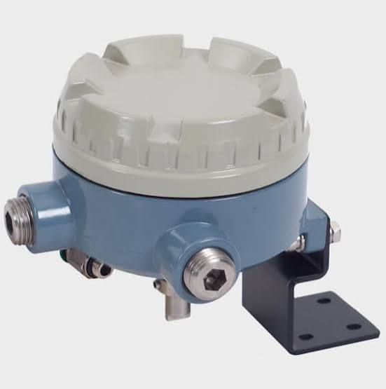
A position transmitter reports continuous valve position to the control system — not just open/closed, but the actual 37% between them. Where a limit switch gives discrete proof, the transmitter gives the curve. It is how a DCS sees a sticking valve before the loop performance degrades visibly.
How It Works
The sensing coupling rides the valve stem lever or NAMUR shaft. Inside the head, a non-contact sensor — Hall-effect, capacitive or a sealed potentiometer — measures the angle; electronics convert it to a signal:
- 4-20 mA, loop-powered — two wires carry power and signal; the universal retrofit choice
- HART over 4-20 mA — adds digital trim, diagnostics and remote zero/span
- FOUNDATION Fieldbus / PROFIBUS PA — full digital status blocks
- NAMUR current steps — discrete fault signalling per VDI/VDE 3845 for 2-wire prox inputs
- Integrated vs standalone: smart positioners already contain this function
- Subsea and severe-duty variants: titanium, double O-rings, depth ratings
Types & Variants
- Standalone transmitter head — retrofits onto actuators without touching the control valve
- Integrated in smart positioner — one device, one calibration (the modern default)
- Linear-travel version — tracks globe/gate stems via yoke linkage
- Redundant / SIL-rated — dual channels with comparison for SIS proof testing
- HART trim — zero/span and characterisation done from the handheld or DCS
- Wireless — WirelessHART boxes for remote, unwired locations
What to Compare Before You Buy
| Parameter | What it means | Why it matters |
|---|---|---|
| Accuracy & linearity | % of span deviation over travel | A transmitter feeding loop analysis must be better than the valve it watches |
| Sensing principle | Contact (pot) vs non-contact (Hall/capacitive) | Contact tracks wear out; non-contact survives vibration and dirt |
| Output & protocol | 4-20 mA, +HART, FF/PA, NAMUR steps | Match DCS cards; HART trim saves a site visit at calibration |
| Loop power & load | Voltage window, permissible load | Standard 2-wire maths: supply minus drop across the loop |
| Certification | Exia/Exd, SIL data, IP/NEMA | Area class and safety-instrumented duty decide the housing |
| Mounting standard | NAMUR shaft or yoke lever coupling | Wrong coupling geometry silently rescales the span |
Where It Is Used
Anywhere the loop must prove and trend what the valve did: high-value throttling loops, SIS proof-of-action with continuous evidence, stuck-valve alarms, signature comparison over time.
- Compressor anti-surge and turbine bypass loops
- SIS partial-stroke evidence between proof tests
- Stuck-valve and drifting-plant alarms in the DCS
- Remote/wireless sites where every trip is expensive
Common Brands
Stonel
Stonel — The severe-service reference: Vykon position transmitters with HART.
Topworx (Emerson)
Topworx (Emerson) — TXP position transmitters across NAMUR and linear mounts.
Azbil
Azbil — AVP positioners with integrated HART feedback. Full profile →
Fisher (Emerson)
Fisher (Emerson) — FIELDVUE DVC families — transmitter function built into the positioner. Full profile →
Siemens
Siemens — SIPART PS2 diagnostics expose position trends over HART/FF.
Rotork
Rotork — IQ3 electric actuators output absolute position over Modbus/Profibus. Full profile →
Field Problems & Fixes
| Symptom | Likely cause | Fix |
|---|---|---|
| Reading drifts over weeks | Potentiometer wear or loose coupling | Prefer non-contact units; re-torque and re-calibrate the coupling |
| 4-20 mA noisy or stepping | Ground loops, shared cable trays, bad shielding | Separate power/screen per spec; check barrier parameters |
| Zero/span off after valve rebuild | Linkage reinstalled at wrong travel ratio | Re-run HART trim or local calibration; verify feedback ratio |
| Moisture inside the head | Failed gland or vent plug | Replace seals; note IP rating only holds if glands are torqued |
| DCS shows a fixed 3.8 mA | Loop fault on NAMUR fault-current logic | Interpret fault current per VDI/VDE 3845; loop-check wiring |
Note. Generic engineering description for education. Brand names above are trademarks of their respective owners; RegValve.com is not affiliated with or endorsed by them. For installation and safety settings, follow the manufacturer’s manual and your plant procedures.