
Hydraulic Valve Actuators
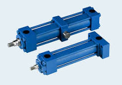
A hydraulic actuator trades air’s convenience for oil’s density: at 200–700 bar, hydraulic pressure packs roughly twenty times the force per area of plant air into the same piston. When a valve needs thrust that no sane pneumatic frame can deliver — subsea HIPPS isolation, large gate valves, hydro plant intakes — hydraulics are the answer.
How It Works
A hydraulic power unit or self-contained pump pressurises oil into the actuator cylinder; directional valving decides open vs close; the fluid returns to a reservoir or a sealed compensator (subsea). Force is oil pressure times piston area — compact but enormous.
- Pressure × area — 400 bar on a 150 mm bore is about 70 kN of thrust
- Linear builds — gate/globe/HIPPS isolation with direct stem coupling
- Quarter-turn builds — yoke kinematics driven hydraulically
- Spring-return hydraulic — fail stroke on fluid loss for SIS/HIPPS
- Subsea compensators — pressure-balanced housings for depth duty
- Self-contained units — onboard pump-accumulator sets where no HPU exists
Types & Variants
- HPU-fed linear — plant-wide hydraulic power unit feeding many actuators
- Self-contained electro-hydraulic — onboard pump; see EHD hub
- Gas-over-oil — gas-charged variant; see gas-hydraulic hub
- Subsea — compensated, ROV-hotstab interfaces, depth-rated seals
- HIPPS / SIS builds — certified spring-return fail action, redundant solenoids
- Manual hydraulic — hand pumps for infrequent large isolation duty
What to Compare Before You Buy
| Parameter | What it means | Why it matters |
|---|---|---|
| Thrust / torque demand | Seat-breaking load at worst-case dP | The whole reason to go hydraulic — size with margin at minimum fluid pressure |
| Supply architecture | Central HPU vs self-contained vs subsea umbilical | Decides cost, response time and maintenance model |
| Fail action | Spring return vs fluid logic | SIS and HIPPS duty require certified fail behaviour with proof-test data |
| Fluid cleanliness | ISO 4406 cleanliness class | Hydraulic valves are unforgiving; contamination is the top failure cause |
| Response & flow sizing | Oil flow to cylinders sets stroke time | Fast HIPPS strokes need real flow capacity, not just pressure |
| Environment | Subsea depth, temperature, fire-safe coatings | Depth ratings and certifications are project-specific paperwork |
Where It Is Used
The extreme-thrust niches:
- HIPPS and high-integrity isolation with certified fail action
- Subsea valve actuation from umbilicals and ROV interfaces
- Large gate and sluice duty in hydro and water control
- Offshore ESD where pneumatic frames would be absurdly large
Common Brands
Biffi (Baker Hughes)
Biffi (Baker Hughes) — HH series hydraulic actuators; subsea and HIPPS packages.
Rotork
Rotork — Fluid-power hydraulic range with subsea experience. Full profile →
Flowserve
Flowserve — Hydraulic actuation for severe-service gate and ball duty.
Severn Glocon
Severn Glocon — Engineered actuation for choke, HIPPS and subsea service. Full profile →
Mokveld
Mokveld — Axial valve actuation matched to their severe-service line. Full profile →
Oil States / Moog
Oil States / Moog — Specialty subsea and high-response hydraulic actuation.
Field Problems & Fixes
| Symptom | Likely cause | Fix |
|---|---|---|
| Sluggish or incomplete stroke | Fluid starvation — pump wear, blocked strainer, low level | Check reservoir and strainer; verify pump output flow, not just pressure |
| Creep under position hold | Directional valve internal leakage or cylinder bypass | Test across-port leakage; service the directional valve |
| Contamination alarms / sticky valving | Oil cleanliness out of spec | Filter to ISO 4406 target; audit sampling procedures |
| Fail stroke fails to complete | Spring pack degradation or blocked return path | Verify return-line sizing; proof-test the spring side |
| Subsea pressure compensation fault | Compensator bladder loss | Inspect compensator and fill; verify depth rating calculations |
Note. Generic engineering description for education. Brand names above are trademarks of their respective owners; RegValve.com is not affiliated with or endorsed by them. For installation and safety settings, follow the manufacturer’s manual and your plant procedures.