
Cavitation vs Flashing: Telling Them Apart and Stopping Them
Two liquid-side damage mechanisms, one root cause — the pressure inside the valve falling below the vapour pressure. Flashing and cavitation are related but behave differently, damage differently, and are fixed differently. This article separates them cleanly and lists the practical countermeasures in order of escalation.
1. The shared root cause
As liquid accelerates through the throttling area of a trim, the static pressure dips to a minimum at the vena contracta and then partially recovers downstream. If the vena-contracta pressure falls to the liquid's vapour pressure Pv, vaporization begins. What happens next decides which mechanism you have:
- Flashing — the downstream pressure stays below (or barely above) Pv, so the bubbles never re-condense. A two-phase mixture leaves the valve.
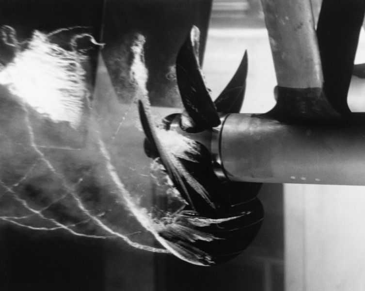
- Cavitation — downstream pressure recovers above Pv, so the bubbles collapse violently against metal surfaces. The implosion jets are what eat trim and piping.
Both phenomena are governed by the same criterion in IEC 60534-2-1: the allowable (choking) pressure drop.
ΔPchoked = FL² × (P1 − FF × Pv)where
FL is the liquid pressure-recovery coefficient of the trim, and FF = 0.96 − 0.28√(Pv/Pc) is the vapour-pressure ratio factor.Interpretation: if your actual ΔP exceeds ΔPchoked, flow chokes and damage risk is real. The lower the FL, the higher the allowable drop — high-recovery trims cavitate sooner.
2. How the damage differs
| Aspect | Flashing | Cavitation |
|---|---|---|
| Downstream state | Two-phase mixture persists | Bubbles collapse downstream |
| Damage location | Downstream of seat, along the flow path | Concentrated where bubbles implode — seat ring, plug skirt, downstream pipe wall |
| Damage appearance | Smooth, polished erosion — like sandblasting with liquid | Rough, sponge-like pitting — metal appears chewed away in patches |
| Noise | Moderate hiss | Gravel-like rumble (distinctive and diagnostic) |
| Capacity effect | Choked flow limits capacity | Choked flow limits capacity + vibration |
The sound test is the fastest field check: cavitation rumbling like gravel in the line is almost unmistakable, while flashing sounds like ordinary high-velocity hiss.
3. The countermeasure ladder
Work down this list in order — each step is cheaper than the next:
- Reduce the operating ΔP. Take more drop upstream (orifice plates, longer letdown trains). Often free at design stage, expensive later.
- Move Pv. Lower the liquid temperature where possible — hot water at 90 °C cavitation-fights far worse than the same water at 60 °C because Pv roughly triples.
- Pick a low-recovery trim. Multi-hole cages, small flow areas and contoured passages raise FL-limited allowable drop and split one big pressure recovery into many small ones.
- Use staged / multistage trims. Stacked disks or labyrinth passages drop the pressure in 4–40 steps, keeping every stage above Pv.
- Cavitation-control (dirty-service) trims. Drilled-hole cages that direct jets to collide at the centre, away from metal walls.
- Protect downstream. A downstream diffuser or resistance plate restores static pressure quickly and relocates any residual collapse away from vulnerable surfaces.
- Hard-face the trim. Stellite, tungsten carbide or ceramics buy time but do not stop the mechanism — treat this as a mitigation, not a fix.
- Move to a different valve family. For extreme drops (e.g. >25:1 per stage impossible), angle valves with venturi outlets, or dedicated multipath/hydrotrol designs.
4. Common mistakes
- Oversizing the valve "to survive". A larger valve at the same ΔP still cavitates — and now spends its life pinched nearly shut, with worse recovery behaviour near the seat.
- Reading FL as a "cavitation index". FL describes pressure recovery for choking calculations; it is not by itself a damage threshold. Incipient cavitation appears at lower drops than choked flow.
- Ignoring piping recovery. A downstream elbow close to the valve adds turbulence and local low-pressure zones — give the valve 3–5 pipe diameters of straight run in severe service.
- Assuming hard trim solves it. Materials change the rate of damage, not the physics.